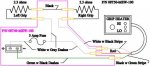
I just installed my heated grips (P/N 08T50-MEW-100) in time for a cool July and August here in Florida, and wanted to share some information concerning the purchase of the attachment kit for these grips, P/N 08T49-MEW-100. I've included my version of a circuit diagram for this attachment kit below. When you purchase the heated grips they do come with an attachment kit, but it isn't the right one for the NT700. A third part is also required, sub harness P/N 05A30-MEW-100.
The attachment kit (P/N 08T49-MEW-100) for the NT lists for around $110. I found, however, that all the parts needed for an install are available in the attachment kit that comes with the grips . . . because I was willing to do some cutting and splicing. The cutting and splicing was a good thing to do in any case as I was able to use tape and heat-shrink tubing to make a very neat install for myself.
WARNING: messing with electricity is not for just anyone! If you have any doubt at all about the circuit in the diagram, or don't understand it completely, or don't know how to identify the positive and negative wires on the sub harness used to get battery power from the electrical system (which you must splice in appropriately), then please DON'T ATTEMPT THIS! I am not responsible for anything YOU do. The sole purpose of this post is to inform you that I did this successfully, and how.
Bill
Attachments
-
 22.6 KB Views: 31