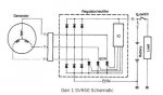
Now back to the alternator wires overheating. I finally realized that the alternator and regulator do not operate the way I would have expected them to. The alternator has no field coil and therefore it’s output cannot be varied, other than by varying the RPM. It basically puts out maximum current and voltage based on the RPM, although the load from the bike’s systems and accessories has an effect, it may not be what you might expect. The service manual doesn’t say much about the alternator but it does state that the regulator/rectifier is “SCR shorted/triple phase full-wave rectification”. The “SCR shorted” is the operative phrase.
When I first glanced at a schematic of a supposedly similar R/R that I found on the internet, I thought I knew how it worked. It looked like a 3-phase bridge rectifier, with switching SCR’s similar to the circuits in a household light dimmer. I should have looked closer because the light dimmer circuitry delays turning on the SCR each cycle to dim the lights. In other words, the more you delay turning on power to the light bulb, on each AC cycle, the dimmer the light. When the SCR is off, there is no current flowing.
Now with the R/R, full available current is always flowing. It starts out flowing to the battery, and bike systems, until their voltage levels reach the reference level (13.1V < Charging Voltage < 15.5V). Then the SCR’s shunt the alternator current back into the alternator through the bridge low side rectifiers (it can’t just turn off the current because a fly-back would occur in the alternator coils and they would arc or get even hotter from the current oscillating back and forth in them). When the SCR’s Short, the excess/wasted energy is then dissipated as heat. There is a voltage drop across the wires, the diodes, the SCR’s, and the connectors. Measure the voltage drop across any of those and multiply it times the current passing through it and that gives the power in watts that must be dissipated as heat by that component. The manual states that the alternator produces 0.438KW at 5000 RPM. Think about how hot a 100W incandescent light bulb gets and then put 4.4 of them together. The current is not continuously being shunted but if the battery is charged and there are few systems powered up then there is a lot of heat being dissipated by the R/R, the alternator, the wires, and the connectors connecting them.
I found this post by DirtFlier from 1/10/2012: “With the engine running, a normally functioning reg/rec is typically too hot to touch with an ungloved hand.” I assume he has touched a good one and it was hot. When I found my alternator wires were hot, I disconnected all of my accessories and the headlight. Not only did it not help, it made it worse because all of those items were no longer dissipating any heat, or using any energy. In fact, when the SCR’s short, the alternator sees the highest load possible, except for during a malfunction like a shorted alternator wire.
Control systems for automation equipment will shunt left over energy through external high wattage resistors called “braking resistors” so that the controller doesn’t overheat. Unfortunately, these R/R’s don’t give you access to the connections between the SCR’s and the diodes which is where the resistors would need to be inserted in the circuits. To make the situation even worse, the new R/R I installed uses FET’s instead of SCR’s. These FET’s supposedly have a lower forward voltage drop than the SCR’s. That makes the R/R run cooler but forces the alternator wires, connectors, and alternator to get even hotter. I cannot touch the crankcase cover for more than a half second it is so hot… but the R/R is cool.
Now I am going to hook everything back up and get serious about voltage and current readings and go from there. I’ll post what I learn and then get back to the MIL 8 issue again.
Sorry for the novel,
Mark