To lube the splines with Molycote 77. Various posting strongly suggest this along with maintenance manuals.
Easy rear wheel removal - no exhaust removal needed
- Thread starter harryhendo
- Start date
OP
OP
Axamax... thanks for the warning. The torque setting for the lower shock absorber bolt and nut is 44 Nm. I updated my original post to show the correct torque settings (from the Haynes manual) for that shock bolt and nut, and also for the axle nut and brake caliper stay bolt.I would like to warn members that I had the lower shock absorber bolt shear whilst riding the bike (2008 NT700)
when it had about 35,000 miles on it. It had never been disturbed. I was lucky that I had gone into a local ex-Honda shop for tyres and the mechanic spotted the shiny part of the bolt. An engineer friend said it had either been overtightened at the factory or the thread cut too deep.
That's for sure, I had so much trouble with it that I ended up removing the driveshaft from the final drive to get it to mate up to the U-joint. The spines are very close fit. You can rejoin the driveshaft with the input of the final drive easy enough.Russ, to assemble the final drive correctly you've gotta hold your tongue just right. You probably missed that part in the service manual.
Mike
If you choose to remove the U-joint from the swingarm, I highly recommend you mark the front of it with a paint pen, and put it back exactly the same way.
I was able to talk to mechanic who fixed my drive shaft alignment and would like to share what I learned which others have done on this worthy forum.
1. Misalignment was caused by drive shaft not seating in far enough. Sometimes you get lucky and it mates and other times not.
2. One can force drive shaft in but future damage could result. Tip can hold in apparently.
3. He likes to apply grease more on ring gear than splines and moves ring gear to make shaft snap into u joints
My additional thoughts:. Marking shaft as stated above sounds like a good idea.
If you could separate pinion joint from shaft via screwdriver and keep shaft fully inside arm arm housing that would be good - may be easier said than done. If rear of shaft ( by spring) is flush with arm/tube housing you have likely seated shaft correctly
Hope some of this may aid all and save you the $96 I spent. Biggest wish is I took it in sooner but after 40 years of fixing I thought I could find it: wrong! Stubborn is not always a good thing. If this saves Mikesim time he owes me a beer for my tongue but suspect it is hard to collect from a Jarhead.
Merry Christmas Russ
Moto-Kafe
Site Supporter
"1. Misalignment was caused by drive shaft not seating in far enough. Sometimes you get lucky and it mates and other times not.
2. One can force drive shaft in but future damage could result. Tip can hold in apparently.
3. He likes to apply grease more on ring gear than splines and moves ring gear to make shaft snap into u joints "
This sounds like Dr. Ruth giving advice to a Couple with "marital problems".........
2. One can force drive shaft in but future damage could result. Tip can hold in apparently.
3. He likes to apply grease more on ring gear than splines and moves ring gear to make shaft snap into u joints "
This sounds like Dr. Ruth giving advice to a Couple with "marital problems".........
Good point brought up here, put the moly on both the driven flange and the ring gear splines. After having to replace the final drive on my NT at my own expense, due to a service error causing rusty/worn splines, I pay particular attention here. Not interested in buying another one. You can clean the old moly off the ring gear with q-tips. I always replace the 3 o-rings back there, and the thrust washer that's underneath the driven flange.3. He likes to apply grease more on ring gear than splines and moves ring gear to make shaft snap into place.
Cleanliness may be next to godliness in many situations, but here is a trick for when a component flops around. Fix it in position with cartridge paper and sticky tape, and then offer it up. The paper will do no harm and eventually will end as dust in the bottom of the housing.
ST1100Y
Site Supporter
- Joined
- Nov 7, 2020
- Messages
- 600
- Age
- 59
- Location
- Vienna, AuSTria, Europe
- Bike
- ST1100Y, ST1100R, NT700
Running ST1100's since '92 I'm pretty anal about drive spline maintenance, thus was quite shocked to find my GF's NT700 parts bone dry, O-rings broken and hub dampers/bushings worn...
Interestingly enough are many ST parts interchangeable with the NT, plus I'd upgraded to polyurethane O-rings quite some time ago, hence had a stash readily available in my shelf...
For those interested: https://redeye.ecrater.com/p/18218041/final-drive-o-rings-for-valkyrie-polyurethane#
Occasionally they also appear on eBay...
ST1100Y
Site Supporter
- Joined
- Nov 7, 2020
- Messages
- 600
- Age
- 59
- Location
- Vienna, AuSTria, Europe
- Bike
- ST1100Y, ST1100R, NT700
LOOSENING JUST ONE MUFFLER BOLT REALLY MAKES THIS MUCH EASIER.
Just finished removing my rear wheel following advice in this post by HarryHendo and NewTo700V.
I'd like to add just one more thing that makes it easier, particularly getting the brake caliper AND brake mounting bracket completely out of the way of dropping the tire out.
(Yes, I have a table lift with a drop out panel, but this same procedure also applies for those who don't and have to remove the rear fender.)
You really have to remove the rear brake mounting bracket from the swingarm in order for the wheel to drop out and not get stuck on the bracket.
Yes, you CAN still do that WITHOUT removing the muffler. As follows:
Perform the steps on page 189 of your owners manual, as follows:
1) Put the bike on the center stand. (Run a tie-down or rope from the front wheel to the center stand so the bike can't move forward off the stand.)
2) Remove the rear fender. (Not required if you have a table lift with a drop-out panel.)
3) Loosen the rear brake stopper bolt
4) Hold the rear axle nut with a 27mm axle wrench or open-end wrench and loosen the axle shaft with a 22mm wrench or socket from the other side.
5) Pull the rear axle shaft out
6) Move the rear brake bracket (with caliper) up and out of the way ***
7) If using a table lift, remove the drop-out panel.
8) Move the wheel to the right to disengage the final drive and then remove the rear wheel.
*** THESE NEXT STEPS ARE THE TRICK TO GETTING THE REAR BRAKE MOUNTING BRACKET OUT OF THE WAY WITHOUT REMOVING THE MUFFLER:
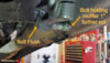
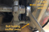
1. Loosen, don't remove, the rear most muffler mounting bolt show in this picture.
NOTE: The nut and large metal washer will drop off of the back of it, so catch those. If you can't get the bolt loose from the front with an allen wrench, remove the nut from the back of it. The bolt does not have to come all the way out, but the nut has to come off the back of it.
This picture shows it completely loosened. This allows the muffler to be pushed away from the side of the bike a good inch!
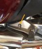
2. Push the muffler to the right away from the bike while you push the brake stopper bolt flush with its swingarm hole as shown in the following picture. With the muffler pushing on it, the bolt will bind in the hole a bit and hold the muffler out of the way.
NOTE: You won't be able to see this bolt going flush with the hole while the brake mounting bracket is still in place. This picture was taken after the fact. But just pull the bolt to the right toward the muffler as far as it will go with the muffler pushed to the right. It will end up flush like this and allow the brake mounting bracket to be removed.
That does three things:
FIRST: It allows COMPLETE and EASY removal of the brake caliper and brake mounting bracket assembly.
(Without doing this, all you can do is pivot the brake mounting bracket, not remove it, and it gets in the way of wheel removal.)
and...
SECOND: It gives an extra 1" of space to get at the axle nut with a standard box wrench. (No need for a special skinny axle wrench.)
THIRD: It gives some extra room to wiggle the brake caliper/brake mounting bracket out of the way.
BOTTOM LINE:
Loosening just one muffler bolt a bit makes this entire job much easier, and particularly makes getting the rear brake caliper and brake mounting bracket in and out much easier.
Just finished removing my rear wheel following advice in this post by HarryHendo and NewTo700V.
I'd like to add just one more thing that makes it easier, particularly getting the brake caliper AND brake mounting bracket completely out of the way of dropping the tire out.
(Yes, I have a table lift with a drop out panel, but this same procedure also applies for those who don't and have to remove the rear fender.)
You really have to remove the rear brake mounting bracket from the swingarm in order for the wheel to drop out and not get stuck on the bracket.
Yes, you CAN still do that WITHOUT removing the muffler. As follows:
Perform the steps on page 189 of your owners manual, as follows:
1) Put the bike on the center stand. (Run a tie-down or rope from the front wheel to the center stand so the bike can't move forward off the stand.)
2) Remove the rear fender. (Not required if you have a table lift with a drop-out panel.)
3) Loosen the rear brake stopper bolt
4) Hold the rear axle nut with a 27mm axle wrench or open-end wrench and loosen the axle shaft with a 22mm wrench or socket from the other side.
5) Pull the rear axle shaft out
6) Move the rear brake bracket (with caliper) up and out of the way ***
7) If using a table lift, remove the drop-out panel.
8) Move the wheel to the right to disengage the final drive and then remove the rear wheel.
*** THESE NEXT STEPS ARE THE TRICK TO GETTING THE REAR BRAKE MOUNTING BRACKET OUT OF THE WAY WITHOUT REMOVING THE MUFFLER:
1. Loosen, don't remove, the rear most muffler mounting bolt show in this picture.
NOTE: The nut and large metal washer will drop off of the back of it, so catch those. If you can't get the bolt loose from the front with an allen wrench, remove the nut from the back of it. The bolt does not have to come all the way out, but the nut has to come off the back of it.
This picture shows it completely loosened. This allows the muffler to be pushed away from the side of the bike a good inch!
2. Push the muffler to the right away from the bike while you push the brake stopper bolt flush with its swingarm hole as shown in the following picture. With the muffler pushing on it, the bolt will bind in the hole a bit and hold the muffler out of the way.
NOTE: You won't be able to see this bolt going flush with the hole while the brake mounting bracket is still in place. This picture was taken after the fact. But just pull the bolt to the right toward the muffler as far as it will go with the muffler pushed to the right. It will end up flush like this and allow the brake mounting bracket to be removed.
That does three things:
FIRST: It allows COMPLETE and EASY removal of the brake caliper and brake mounting bracket assembly.
(Without doing this, all you can do is pivot the brake mounting bracket, not remove it, and it gets in the way of wheel removal.)
and...
SECOND: It gives an extra 1" of space to get at the axle nut with a standard box wrench. (No need for a special skinny axle wrench.)
THIRD: It gives some extra room to wiggle the brake caliper/brake mounting bracket out of the way.
BOTTOM LINE:
Loosening just one muffler bolt a bit makes this entire job much easier, and particularly makes getting the rear brake caliper and brake mounting bracket in and out much easier.
Last edited:
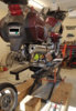
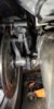
Hi Guys, greetings from the UK. Took the rear wheel out of my NT700VA-8 recently and got my shock rebuilt (no damping). I didn't have a problem refitting the wheel on the previous occasion but this time I am stuck as I cannot get the hole in the caliper to fully line up and allow the axle through. As you can see in the photo either the caliper needs to move down a bit or the wheel nees to come up a bit. I've tried levering under wheel with plank and also pushing down on top of caliper but still can't line it up enough to get axle through . Anyone have any tips/tricks ?
Best regards
Mike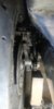
Best regards
Mike
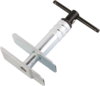
From the picture it appears the outer pad is twisted slightly and catching the edge of the rotor, try pushing the caliper pistons in a bit more.Hi Guys, greetings from the UK. Took the rear wheel out of my NT700VA-8 recently and got my shock rebuilt (no damping). I didn't have a problem refitting the wheel on the previous occasion but this time I am stuck as I cannot get the hole in the caliper to fully line up and allow the axle through. As you can see in the photo either the caliper needs to move down a bit or the wheel nees to come up a bit. I've tried levering under wheel with plank and also pushing down on top of caliper but still can't line it up enough to get axle through . Anyone have any tips/tricks ?
Best regards
Mike
Be sure to pump up those brakes when done.
ST1100Y
Site Supporter
- Joined
- Nov 7, 2020
- Messages
- 600
- Age
- 59
- Location
- Vienna, AuSTria, Europe
- Bike
- ST1100Y, ST1100R, NT700
This comes quite handy:From the picture it appears the outer pad is twisted slightly and catching the edge of the rotor, try pushing the caliper pistons in a bit more.
Absolutely! Good advice though...Be sure to pump up those brakes when done.
Hi thanks for that - its exactly what I was thinking too having looked at the photo , that next attemp it is spead out pads again !From the picture it appears the outer pad is twisted slightly and catching the edge of the rotor, try pushing the caliper pistons in a bit more.
Be sure to pump up those brakes when done.
I pulled the caliper right off again and I think I found the problem I believe I fitted the "pad guide" (the metal clip at other end from pad pin) the wrong way around - hence the gap for the disc to fit through as not where its supposed to be and so the disc couldn't fit through. 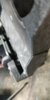
c
Hallalujah - all slipped in nicely once I had turned that pad pin around ! Always good to tell someone about it , then you have the "hallalujah" moment ! Will take her for a spin tomorrow and see if the shock rebuild has worked !
Attachments
-
 75 KB Views: 12